Over the years, I have written hundreds of prototypes that range from a tiny program to calculate a small bit of math, to an almost entire level editor and game, just to flesh out an idea. On other occasions, I create small prototypes in DarkBASIC Professional[/b] to try out new technology, and increase the support for the cool devices that are out there to play with. One of my more recent series of technology enhancing tweaks has been stereoscopic support.
There has been a recent surge in the sophistication of stereoscopic devices, and one of the coolest pieces of kit to own is a stereoscopic LCD display. Costing a little more than a standard LCD, you plug in your graphics card, wear a pair of lightweight wireless glasses and watch as your images pop out at you.
In true bleeding edge style, TGC have worked to develop support for one such device, namely the iZ3D LCD monitor. A new command has been added to the latest upgrade to DBPro to allow the generation of stereoscopic buffers. In addition, a new flag has been added to set display mode to allow double wide backbuffers to take advantage of multi-monitor functionality.
The stereosopic technique is straight forward. Instead of rendering a single camera to the backbuffer, you render two cameras, one from the perspective of each eye. You render the first camera to the left side of a double wide backbuffer and the second camera to the right side of the double wide backbuffer. The device will then take these two source images and feed them to the user using whatever mechanism is needed to get the left image to the left eye and the right image to the right eye.
The iZ3D technology does this by combining the left and right images together and placing them on the LCD display, together with a polarization mask which works together with the glasses to reveal the correct image to the correct eye.
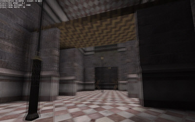
Polarised 3D image in DarkBASIC Professional
An example program has been provided which shows a typical FPS scene with mouselook controls. The example creates a double wide backbuffer with the following lines of code:
set display mode desktopwidth,desktopheight,desktopdepth,vsync,antialias,multimon
set camera view 0,0,0,desktopwidth*2,desktopheight
When the variable ’multimon’ is set to 1, it instructs the command to create a backbuffer twice the size of the display resolution of the desktop. This example uses a full desktop window rather than full screen mode, and the second command stretches the application window to encompass both the current monitors display and a ’theoretical’ monitor to the right of the main display. If you have a multi-monitor system, you will notice the polarization mask displayed on your second monitor. If you had an iZ3D LCD display, this second display would be used by the polarization hardware to change the main display to allow the glasses to do their work.
The next set of commands in the example are used to create the cameras that will be used to represent the eyes of the viewer, and feed the render of those cameras into images 1 and 2.
make camera 1 : set camera to image 1,1,desktopwidth,desktopheight
make camera 2 : set camera to image 2,2,desktopwidth,desktopheight
Once we have the left camera image and right camera image, we can feed those images into the stereoscopic command as follows:
set cameras to stereoscopic 1,1,2,3,4
This will combine the two images and generate the polarization mask that we need to feed into the iZ3D device.
The remaining code before the main loop will create two sprites which we will use to render the final stereoscopic images to the double wide backbuffer, load the 3D scene so we have an environment to move around and create an invisible object we can use to help position the cameras based on the position and orientation of the viewer.
This invisible object is made up of a central sphere and four child spheres. The first two child spheres represent the eye positions of the viewer. The second two child spheres are the locations each eye camera looks towards. With all spheres invisible, we can use their world positions to easily position and point the left/right cameras, rather than rely on complex matrix calculations. The whole object is repositioned when the viewer moves and rotates, so we can use ’limb position’ commands to get the latest position of the viewer and the direction the viewer is looking.
Three variables called ’eyeswide#’, ’focalpoint#’ and ’focaldepth#’ adjust the relative positions of these invisible spheres and in turn, control the cameras that are associated with them. By adjusting the cameras, you can control such details as the depth of the stereoscopic scene and whether the scene will sink into the monitor or pop out at you.
Combined with mouselook controls, the above code positions and rotates both cameras and produces the images required for the final render step.
The final rendering process happens in two steps. The first step is to render the latest views from each camera to their assigned images (1 and 2). This is done with the following code:
sync mask %110 : fastsync
The ’sync mask’ command instructs the ’fastsync’ rendering command to ignore camera zero, but perform renders on camera one and two (our two eye cameras). Camera zero is going to be used in the second step. It is also worth noting that during the rendering of the eye cameras, the command ’set cameras to stereoscopic’ kicks in as soon as the left and right eye images are available. This command triggers the generation of the combined stereoscopic image and the polarization mask which are stored in images 3 and 4.
In the second step, we will render the final stereoscopic images to the double wide backbuffer. We previously set up two sprites with images 3 and 4 and placed them off screen. Sprites in DBPro act as perfect screen space quads and so are ideal for pasting images directly to the backbuffer. We use the ’paste sprite’ command to paste a copy of the prepared ’left’ sprite to the left side of the double wide backbuffer and the ’right’ sprite to the right side of the double wide backbuffer. With the backbuffer completely filled in, we can then write some debug text for our minimal HUD text. The following code will render the above to the main display:
sync mask %1 : sync
We use camera zero as our main display camera and not as a 3D camera. We use camera zero to paste images and text to the backbuffer. The final ’sync’ command presents the final result to the monitor and the loop returns to the beginning.
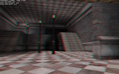
Anaglyph 3D image in DarkBASIC Professional
Using the above technique, you will be able to add stereoscopic support to your creations very easily. That said, there is no substitute for seeing the results for yourself. Being able to peer inside your monitor, or have the nozzle of a beefy gun stick out of your LCD is a sight not to miss.
For more information on the IZ3D LCD monitor, you can visit their home on the web HERE (http://www.iz3d.com).
If you are lucky enough to own such a monitor, for this example to work, you will need to disable the iZ3D drivers as DBP uses native support and their drivers will conflict. Also ensure you do not use clone view, and set your monitor up to extend your desktop to the second internal display (Dual View).
For those of you who cannot quite afford to buy a new LCD right now, there is also an anaglyph (red/blue) version of the example that accompanies this article.
May I be the first to say, welcome to the world of stereoscopic gaming!
The files for the projects discussed can be downloaded HERE[/b], and you can learn more about DarkBASIC HERE[/b]. We will be answer questions about using our engine for stereoscopic 3D compatibility in this MTBS forum[/b].
Read full article...