Thank you for participating with the iZ3D/MTBS/CGArena CG Graphics Stereoscopic 3D Photo contest. This is your chance to take your virtual 3D art, and let people see it in TRUE 3D!
More likely than not, your work is being rendered in volumetric 3D that is shown on a 2D display. This contest is focused on stereoscopic 3D which means your images are shown on true 3D media including 3D monitors, HDTVs, projection screens, and more. To accomplish this, you will need your CG art submitted as two unique images that were captured from two different camera or viewpoint positions.
However, that’s not where it ends! The S-3D is part of the art itself and your work will be judged on its effective use of stereoscopic 3D. Is the S-3D complementing the art somehow? Are you evoking a mood or reaction from your work? Is it a comfortable experience? These are all factors worth considering.
While easy to follow, this guide is written for the CG artist who wishes to pay more attention to S-3D detail.
Part One: Understanding the S-3D Visual Map
The Possibilities
There are three types of 3D experiences you can create:
1. Depth 3D where you can see into the screen like a car windshield, but nothing ever penetrates the glass.
2. Pop-out 3D where things seem to fly out of your monitor’s window, but you see very little depth in the distance.
3. Depth 3D and Pop-out 3D where you benefit from both experiences.
If you already understand how the stereoscopic 3D visual map works, please skip to “Part Two: Capturing and Manipulating S-3D Images”.
The Stereoscopic 3D Visual Map
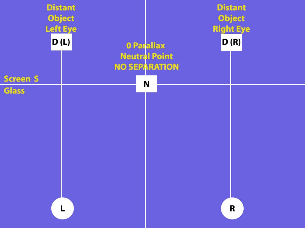
When viewing a completed stereoscopic 3D image with S-3D hardware, this top view diagram explains how your eyes interact with the virtual 3D environment:

Circles “L” and “R” are your left and right eyes.
The “S” line is the virtual screen glass. Professionals call this “Zero Parallax”, but we will call it the “Neutral Point” because everything behind this position appears in the distance, and everything in front of it is an out of screen effect and will appear to pop out at you! Lots of fun! This is a virtual line and is not representative of your monitor’s physical screen location.
To make this easier to follow, symbol “D” refers to “distance”, and “P” refers to “pop-out”.
Let’s see how everything relates!
First, the boxes all represent the same object, but from different 3D perspectives. Remember that when you are wearing 3D glasses, your left and right eyes each see a unique 2D image, and your brain combines the two to create the 3D experience. This diagram is showing what things look like without the 3D glasses on so you can follow the relationships.
Box “N” is your object at the “Neutral Point” or “Zero Parallax”. If you were looking at this with your naked eye without 3D glasses, it would be a single box because there is absolutely no separation to create a 3D effect. If this was the only thing on the screen, it would appear to be 100% flat.
Box D(L) and Box D(R) is the same box with a space in the middle. This space is called “separation”, and the 3D distance is determined by the amount of separation between D(L) and D(R). If you were wearing 3D glasses, your brain would take these two images, consider the separation between them, and create a deep 3D experience for you.
Notice how D(L) and D(R) are aligned with your left and right eye? For the depth sensation to work, it is important that the image matches the eye that is seeing it. For example, if you open just your left eye, you will see D(L), and if you open just your right eye, you will see D(R).
It is important that the separation does not go beyond the actual space between your eyes or you will experience something called “divergence”, or encourage your eyes to point uncomfortably apart from each other. Also, the space shown in this diagram is exaggerated in two respects. First, the separation is usually no more than an inch to two inches apart for distant objects. Second, when the images have the same separation as the distance between your eyes, it is as though you are looking into infinity which is unlikely to happen in most photography experiences.
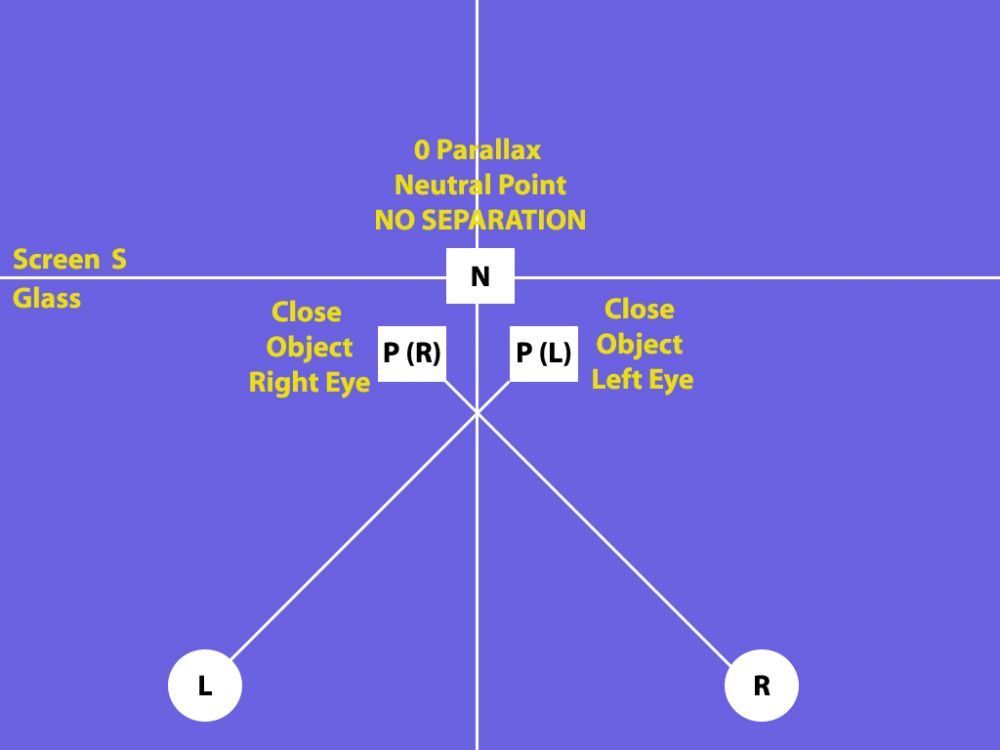
P(R) and P(L) is also the same box, but if you were wearing 3D glasses, it would appear to be popping out at you! How is this feat accomplished? If you look at boxes P(R) and P(L), their perspectives are crossed from D(L) and D(R) – everything is opposite! If you opened just your right eye, you will see P(R), and if you open just your left eye, you will see P(L). In both cases, these are opposite perspectives of where your eyes are accustomed to seeing things.
Separation impacts this pop-out effect too, and the space between P(R) and P(L) tends to be less than D(L) and D(R) because the pop-out will be distracting and unattractive if overused.
We can simplify these terms even more. Think of separation as your depth budget, and convergence determines how much of that depth is spent on going inside the screen, and how much is spent going outside the screen.
As a digital S-3D photographer, you have the flexibility to choose where line S or “Zero Parallax” is so you can create the 3D experience you want.
Pictures in Action
Let’s take a look at the three different 3D scenarios using video game images. There is a wide selection of far superior full color stereoscopic 3D solutions out there, but for our purposes, we are going to demonstrate these concepts using anaglyph red/blue images. With the colors, you will be able to see how the visual elements relate to each other.
In the case of anaglyph, the red side goes over your left eye, and the blue side goes over your right eye. The images are captured from Fear Combat by Sierra.
1. Depth 3D
Depth 3D is where you can see into the screen like a car windshield, but nothing ever penetrates the glass.
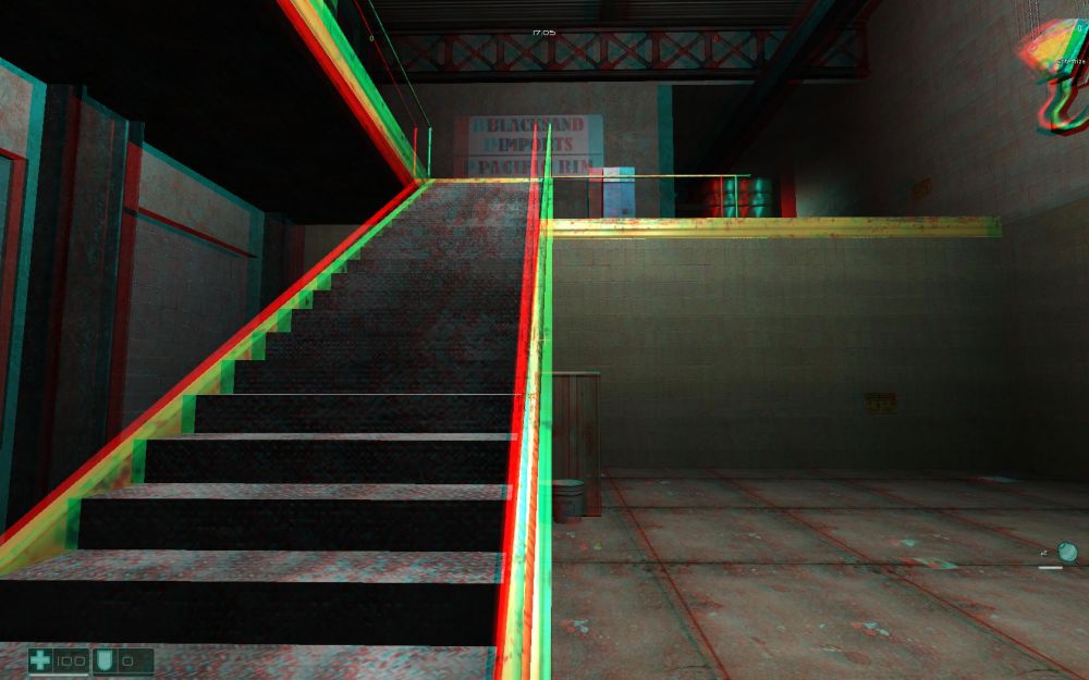
Look carefully at the staircase. Remember, everything in red is what your left eye sees, and everything in blue or with a blue tinge is what your right eye sees.
The further into the scene you look, the further apart the separation or the doubling is. Meanwhile, as the scene gets close to your personal space, the images join together. This is an example of a depth-only stereoscopic 3D experience.
Looking at the diagram, the back of the room is in positions D(L) and D(R), and the bottom of the staircase is in position N. Nothing goes beyond the S line which is why you don’t get the pop-out sensation.
2. Pop-out 3D
Pop-out 3D is when things seem to come out of the monitor, but the background is flat.
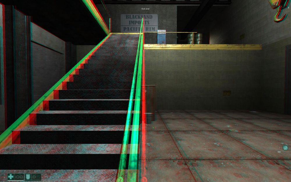
Look at the back wall on top of the staircase. There is zero separation in the distance, and therefore, there is no depth to be seen in the background parts of this picture.
Now look at the staircase. Notice how it separates more as the image gets close to you? Unlike the earlier photo which showed depth by having the red color on the same side as your left eye, this shows the red color on the opposite side where your right eye would normally be looking. This cross-eyed technique is what creates that pop-out effect.
Looking at the diagram, the entire background is in position N, and the remaining elements are in P(R) and P(L). This is a pop-out only scenario where the staircase seems to be coming out of the screen from an otherwise flat room.
3. Depth 3D and Pop-out 3D
This is a scenario where you get a mix of both a sense of depth and a pop-out experience.
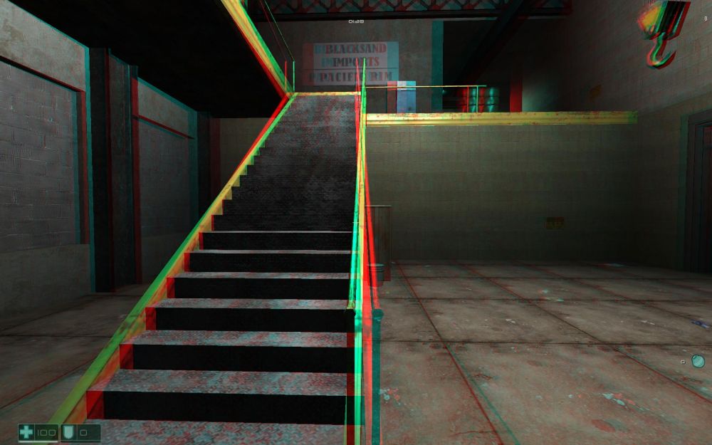
This image gives you the best of all the elements. If you look at the back wall on top of the staircase, there is separation between the images. The red is on the left, the blue is on the right, and this is in line with each of your eyes. This image will give you a sense of depth for the rear part of the scene.
Up close, the colors have switched over, and the red is on the right and the blue is on the left. This is the opposite of what your eyes are accustomed to seeing and this flip over creates the pop-out effect for the objects up close like the top of the banister at the bottom of the stairs.
Look at the banister of the staircase very carefully. About halfway up, there is a cross-over point where the colors switch over. This crossover makes the banister look like an X. The center of this X is called “Zero Parallax” or what we called the “Neutral Point”. When you are adjusting your stereoscopic 3D experience, you can determine where that “Neutral Point” or “Zero Parallax” location will be, and this is done by adjusting something called “convergence”.
Looking at the diagram, the back of the room and top of the staircase is in D(L) and D(R). The middle of the “X” part of the staircase is on N. The bottom of the staircase is in P(R) and P(L). The staircase is an example of an object that crosses the “Zero Parallax” or “Neutral Point” threshold and exists in both plains.
Part Two: Capturing and Manipulating S-3D Images
Earlier in this guide, we talked about how a final stereoscopic 3D image should look in different 3D scenarios. This section will briefly explain how to create the left and right images to get the S-3D outcome you want.
While you may have the flexibility you need in your CG application, we recommend the free stereo photo maker found HERE as part of your stereoscopic 3D image creation process.
1. The Stereoscopic 3D Image Capture Map
Earlier in this guide, we were able to show a map of what S-3D images look like when seen on 3D monitors and devices. The following is the S-3D Capture Map, and this explains how 3D images can be captured and adjusted to your liking. This is a simplified explanation, but it should meet your needs:
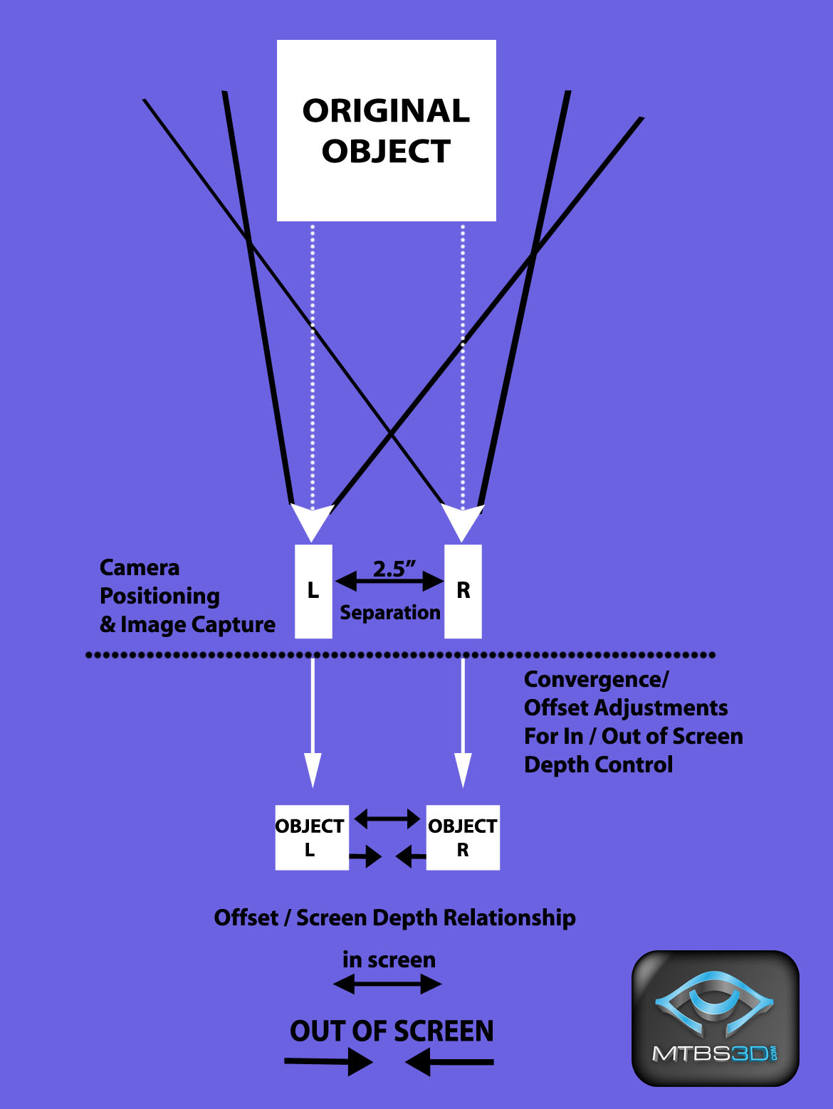
This map works in two steps. The top half refers to the physicality of camera placement, the separation between the cameras, and the actual image capture. The bottom half is the post-production step of offsetting the images to adjust convergence and determine how far in or out of the screen your 3D object will be.
Follow these instructions to get the results you are after:
Depth Only
• As shown on the above S-3D Image Capture map, create two unique viewpoints or cameras with a “separation” of 2.5 inches in your CG application - 2.5 inches is the average distance between human eyes. The cameras should be at the virtual distance from the object you would expect human eyes to be if they were part of the 3D environment. Make sure the cameras are parallel and are facing straight north. Never “toe-in”, or angle your cameras inwards as this will create visual distortions.
• Try to create a virtual window between your cameras and your object with the dimensions of a 22” 16:10 aspect monitor. This window should not appear in your capture, but will be a reference tool to determine if your cameras are appropriately close or far from the object. The window must not be seen in your capture, so you may have to delete it once you are done with your adjustments.
• Depending on how close your object is to the cameras or viewpoints, there can be some pop-out or out of screen effects.
Adjusting the In/Out of Screen Effects (the “Pop Out Effects”)
As shown on the S-3D Image Capture Map, once your cameras are laid out and the images are recorded, the viewpoints need to be proportionately offset or shifted to adjust the convergence or “pop-out” effects to your liking:
• When your left and right image are shifted in opposite directions or away from each other, the depth of the whole scene is increased, your scene looks as though it is deep inside the monitor, and the out of screen effect is decreased.
• When your left and right image are shifted towards each other or inward, the depth of the whole scene is decreased, your scene looks as though it is coming outside the monitor, and the depth inside the screen is decreased.
Some important points:
• When offsetting your images, the cameras are not being moved or angled in any way. This convergence step is happening after the images are captured from the virtual cameras.
• When offsetting your left and right images in either direction, you are cutting off a portion of your image too. You can overcome this by either equally increasing the field of view in each camera, or making sure there is enough buffer space around your images so the offset does not take away from what you are trying to capture.
• You may find it necessary to increase or decrease your “separation” to compensate for your convergence adjustments. For example, after adjusting for your “pop-out” effect, you may find the over-all separation is too low and retake the images with your cameras wider apart. We recommend avoiding this adjustment unless you can visually test your results with 3D glasses.
Unless your CG software can do this for you, here are instructions to follow with the free stereo photo maker software:
I. Save each camera image independently from each other in the same resolution and color depth. We require resolutions no less than 1680X1050 per camera, with a 16:10 aspect ratio. Make sure you label each image file name with an “L” or “R” to indicate if it’s a left or right sided image. If the images get reversed, this creates visual problems!
II. Download and run the free stereo photo maker HERE[/b].
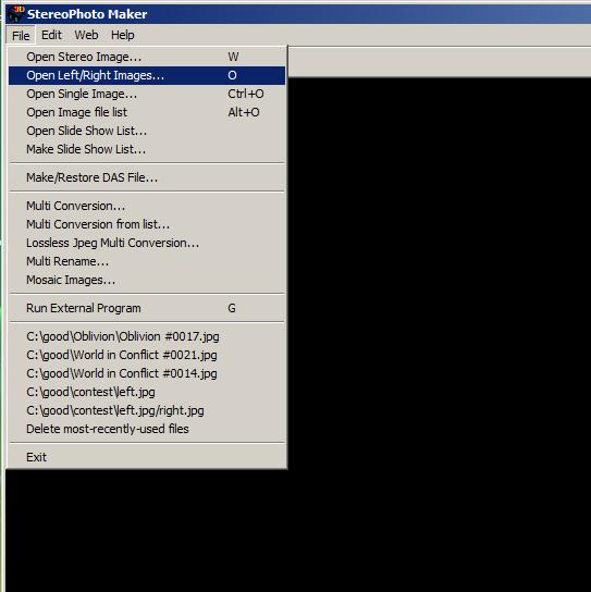
III. Load the images as a “left” and “right” sided image by choosing “Open Left/Right Images” from the file menu and using your images labeled “L” and “R”.
IV. From the “Stereo” menu option at the top, select “Adjustment View” (F5 key):
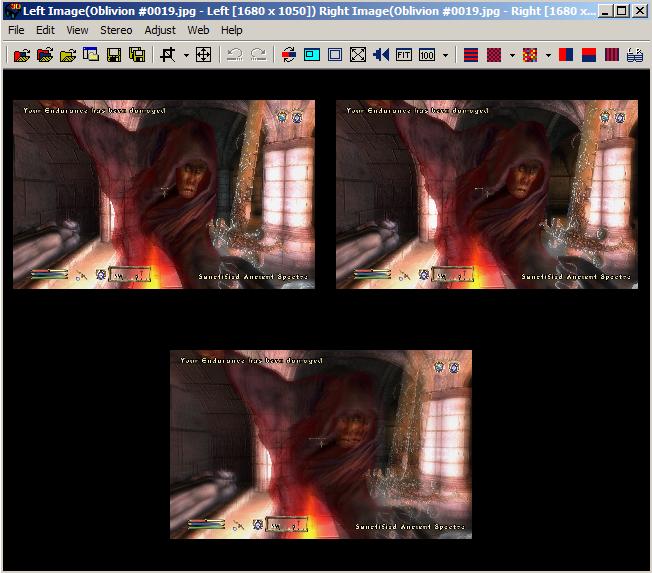
You will see your separated left and right view at the top, and the overlapped S-3D view at the bottom. When you press the left or right arrow keys, the images offset in the appropriate direction.
a. Pressing the “left” arrow key offsets the images in the opposite direction, and enhances the depth or “in screen” experience.
b. Pressing the “right” arrow key offsets the images towards each other, and enhances the “pop-out” or “out of screen” experience. Pay close attention to the furthest part of your image(e.g. a back wall) in the preview image at the bottom – you have reached your maximum convergence or “pop-out” experience when this back part is uniform or completely joined together.
V. If you don’t yet own a stereoscopic 3D hardware solution, you can buy an inexpensive pair of anaglyph (red/blue) glasses. Anaglyph is the worst way to view S-3D photographs, but this is just a quick test to determine if your separation and convergence settings are appropriate. In the “Stereo” menu option, choose “Anaglyph” (F7 key), and you will be able to view your image in red/blue format.
By alternating between the Adjustment View and Anaglyph View, you will be able to preview and adjust your image on the go. For best results, try previewing on a monitor that closely matches the media this contest will be displayed on – in this case a 22” monitor.
VI. When you are pleased with the results, switch back to “Side by Side” viewing, and save your image in the File submenu by selecting “Save Stereo Image”. Make sure the image is saved in full color and not red/blue anaglyph!
Image Backgrounds
If you want to add a background for your image, you must render it as an object in your scene. For example, if you want to render a back wall, you need to lay out your objects, place a wall at the appropriate distance behind them, and capture all the elements in a single step. If you try to add the wall separately as an add-on 2D object, your entire scene depth will be incorrect.
Avoid trying to render 2D terrain as a background for your objects. For example, mountains will only look like mountains if they are indeed rendered in 3D.
Final Remarks
Submit the side by side image as a 24 bit BMP file. If the image is correctly recorded, it should be double the width, but the same height as a single camera image. For example, if each camera is recorded at 1680X1050 pixels, the submitted file should be 3360X1050 in size.
Special thanks go to John Merritt and Oleg Tishutin for helping make this guide possible.
That’s it! Have fun and good luck. Results will be announced at SIGGRAPH 2008. Be sure to visit our main site at http://www.mtbs3d.com[/b] and play a part in shaping our industry!
Read full article...