With all the buzz surrounding nVidia's new LCD shutterglasses system, this setup may seem like a step back to some. However, I actually chose to build this after nVidia made its announcement of the shutterglasses system, since A) I am not going to buy Windows Vista and B) I am not going to upgrade my LCD display. I have a large library of older games (now about 100 games) that I have not played due to grad school responsibilities. I have a little more time on my hands now, and I can start to enjoy those old games, so I decided to try to get them to run in stereo3d to get the most out of them.
I have an older computer system (single core 3.2ghz PIV, WinXP) and my 19" CRT died about 6 months ago. I had a backup 15" XGA resolution LCD monitor and, although the screen size is small by today's standards, all those old games (many of which have a maximum resolution of 1024x768) will run fine on this monitor. My CPU is slow by today's standards, but is fine for those older games at XGA resolution. The fill rate provided by the 7950GT allows me to game in stereo3d with no noticeable loss in frame rate in comparison to the card it just replaced (256MB ATI X800XL). I am running the 93.71 driver pair.
So anyway, after seeing nubie's posts on the nVidia and MTBS3D forums, I decided to go ahead with the stereomirror build. First, I had to verify that my LCD was 45/135 degrees polarized. After confirming this, I ordered a duplicate of my monitor on Ebay.
As I stated before, when I sketched out the plans for the build I decided I needed three things. First, I wanted the stereomirror cabinet to be height-adjustable, since I wanted to be able to tweak the viewing position after I had it set up. Secondly, I wanted the rear LCD monitor to be able to "nest" in the back of the cabinet while still remaining attached to its base. This would allow me to remove the cabinet and use my back LCD monitor without any disassembly of the cabinet or components, should the need arise. Thirdly, I wanted light/reflection control, so as to best isolate the stereo image.
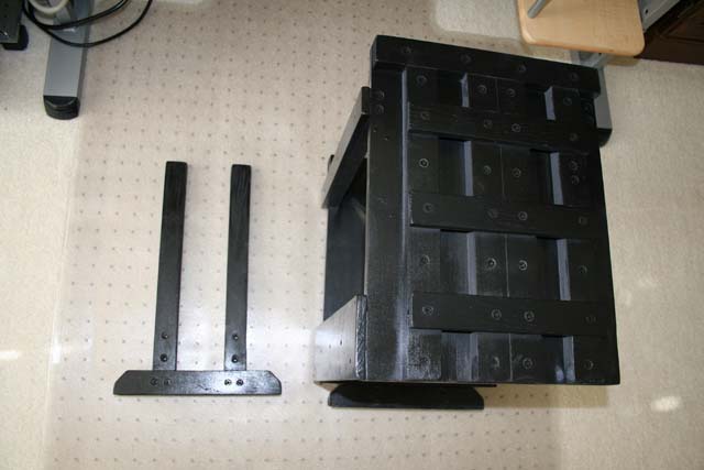
The basic design of the cabinet is the same as others you see on the internet, so I will not repeat them here. Instead, I will just focus on the things that I think make my cabinet different, so that others may use them and/or get different ideas to improve on the concepts. Here is the basic design of the cabinet, with a pair of adjustable sliding legs whose posts were made up of 0.75" x 1.5" wood pieces. Note that the "guide rails" that were attached to the cabinet were cut from the same dimension wood.
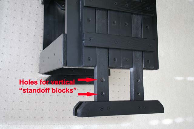
The leg posts slide right into the side rails (image below). Note the holes drilled for vertical height adjustment "standoff blocks".
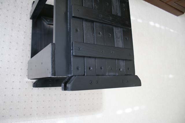
The legs fully seated (image below).
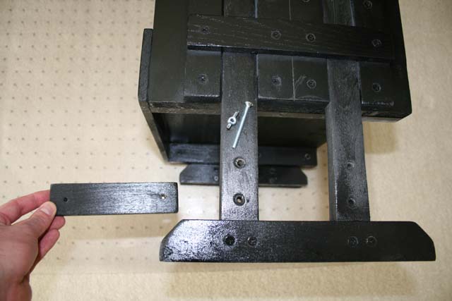
The "standoff blocks" used to increase the height of the cabinet, secured in place with bolts and wingnuts (image below).
Two standoff blocks in place, providing 3" of additional height, if necessary (image below). The opposite leg is shown without blocks installed.
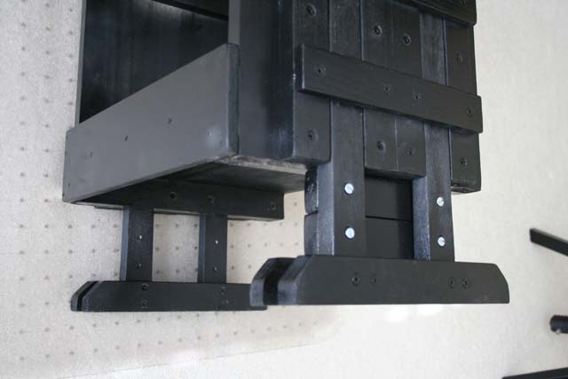
The finished cabinet, with one standoff block in place on each side (image below).
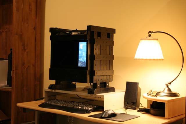
The rear LCD monitor (image below), "nests" into the back of the cabinet up against support rails, which hold it in the proper front/back ("z axis") position. There is barely 1/16" of extra space for the monitor vertically and horizontally ("y" and "x" axes), so it fits snugly in one consistent position. The cabinet can be removed from the desk in about 30 seconds, leaving the back monitor in place on its own original stand.
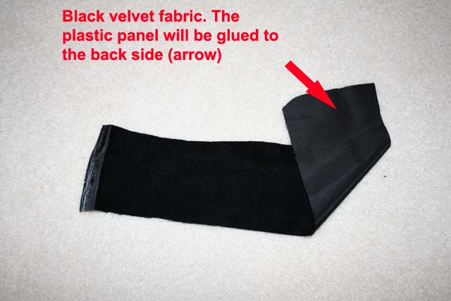
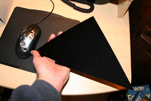
Finally, I want to share what I did for reflection/light control. A few years ago I built some masking for my projection screen, using black velvet, which is known for absorbing scattered light. I utilized it in this situation as well, inside the stereomirror cabinet. However, I did not want to glue the velvet directly to the inside surface of the cabinet, since an occasion may arise in which the velvet gets dirty (like if I sneeze on it
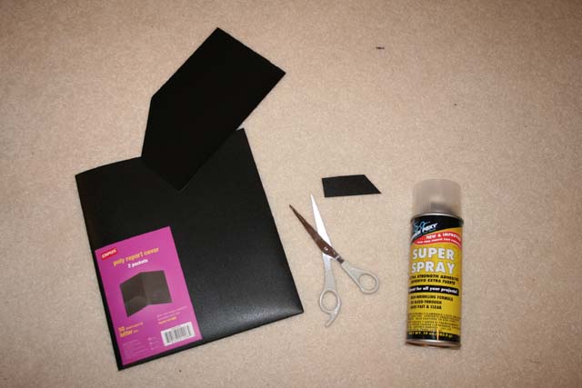
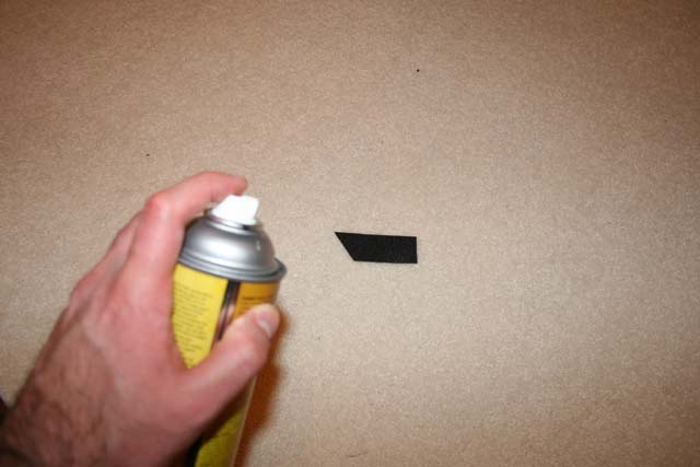
Keeping the black velvet at the ready, I used a spray adhesive to coat one side of the plastic panel (images below).
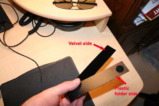
After the panel has a good coating of adhesive, lay the sticky side on the back of the velvet fabric swatch (image below).
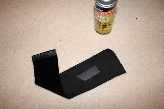
After the glue has been allowed to dry overnight (to be safe), you can now simply cut out your plastic panel from the velvet fabric. You now have a custom-fitted velvet panel, which will absorb light like no other surface. See the images below, which shows how black velvet soaks up direct and reflected light. Its actually difficult to photograph the interior of the cabinet because the velvet absorbs light and all details of the interior construction are lost!
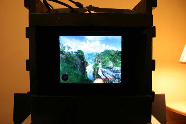
Far Cry in all its stereo3d glory

Some important things to remember:
Before you draw up a blueprint, first see what dimensions of wood you have available at your local lumber yard or hardware store, as this will influence your blueprint and calculations of cuts needed for the lumber. At a store called Menards in the USA, very high quality shrink-wrapped lumber is offered, which is of consistent dimensions. However, MEASURE THE WOOD before you buy it, since the advertised dimension may not match the actual dimension (sometimes they print "actual dimensions" in the fine print on the craftsman-quality shrink-wrapped wood).
Be careful if you have the hardware store cut your wood to length. Some people who work there do not really care about the quality and precision of the cuts they make. I had one guy who would not allow the circular saw to spin up to its top speed before making the cuts--and the result was chewed-up, splintered wood edges. After this experience, I elected to only have the large 12" wide side pieces of the cabinet cut by the hardware store, the rest I cut myself with a hand saw.
Label the wood pieces! My design was made up from more pieces of wood than normal--and you want to make sure you label front/back, top/bottom, and left/right for everything as you are cutting pieces to fit. Minor variations in the wood dimensions may cause a lot of frustration...pieces that fit a moment ago but suddenly do not (or screw holes that suddenly do not line up anymore) may have simply been flipped around or switched with the piece from the contralateral side. Label everything!
The 50/50 mirrors are definitely more expensive (I think I paid a $50 premium over a 60/40 for my small mirror). I cannot comment on whether a 60/40 would have been a better cost-versus-performance purchase, but I saw that Planar uses 50/50 mirrors, and given the amount of work I put into this (and all the games I was going to play on it), I did not want to skimp. The 50/50 mirror was also thinner (1/8" thick, versus 3/16" for the 60/40), which may reduce refractive image distortion, but I can't confirm this without a direct comparison.
The half-silvered mirror does not have to be the full hypotenuse dimension between the monitors; do a direct view measurement to see how much you really need, with a little extra for safety and adjustment purposes (you can always mask out any slight excess you have with a long strip of black velvet panel). For my small 15" LCD setup, I used an 11.5" high mirror.
This brings us to another important point regarding the mirror: if you base the horizontal dimension of the mirror on the actual width of your LCD monitor frame (to make the cabinet design a little simpler), be sure to check the fit of the mirror in the cabinet BEFORE you glue any wood down (which is what I did to back up the wood screws I used). Remember that the mirror is positioned at a 45 degree angle, and that it traverses both the horizontal and vertical dimension of your cabinet. If your cabinet "tapers" a little in any dimension, you may have a heartbreaking moment where your mirror begins to slide into place, then gets stuck before being seated in its final position--which almost happened to me! Cutting 1/8" off the edge of an expensive mirror to get it to fit would be a nerve-wracking experience, and may result in a fractured mirror. The safe thing to do is to order your mirror a fraction of an inch narrower than your LCD frame width. If you still find that your cabinet is constricted at any dimension, you can add circular metal washers between the wood pieces (over each screw tip after it pierces the first piece of wood) to act as spacers, then fill in any gap with wood filler putty.
When you build the wood cabinet, periodically check the fit of the monitors in the cabinet. My fit was so tight that once I spray painted and clear-coated the cabinet, the upper LCD almost had to be forced into place. Luckily, I was so careful with my measurements the stereo images lined up perfectly in both dimensions (the vertical is more critical for stereo3d configuration, since the horizontal will change anyway with your stereo3d settings). I actually did want the top monitor "fixed" in one position, so that any stereo image adjustments would just need to be done by moving one monitor (the back monitor). If some people do a build and find that they have a little more wiggle room around the LCD's than necessary (which would allow a greater margin for image adjustment), the monitor position(s) could be fixed in place using stick-on felt pads (the ones you can buy for furniture legs so they don't scratch the floor) or another material to "wedge" the monitor frame in the proper image-corrected position. This, however, may introduce a gap that lets light in, depending on your cabinet design and the amount of adjustment space you have.
The sliding leg system was built by lining up the rails and the leg posts at the same time, and then screwing down the rails, leaving the leg posts free to slide. This creates the proper dimension for the sliding leg posts (since the actual leg posts are used to define the position that the rails are screwed down at). However, it is possible for the fit to be too tight. When you finalize the construction of the sliding leg posts (after you have affixed the rails to the cabinet), you need to then sand down the leg posts on every surface or they will bind in the sliding channel after you are done painting (I think this has to do with slight distortion of the multi-piece design as you place screws in it). The "side" surfaces of the leg posts will need to be sanded no matter what, but as an alternative to sanding the "front/back" surfaces of the leg posts, you can place some spacers (like some small coins or metal washers) between the aligned post and rails (on just one side for each leg post) while you screw the wood rails in place. This effectively creates a small space for the leg posts to glide across (once the spacers are removed), and gives room for paint and clear coat. Remember to label the leg post wood as you contruct them (left/right side, top/bottom, and front/back)!
The spray adhesive I used cost $5 and worked fine, there are more expensive ones made by 3M ($15 or more) but I do not think they are worth it.
When configuring the stereo3d drivers, I chose the "Clone" mode under the nView Display Mode menu (note that depending on how you have your LCDs plugged in, you may need to change the Primary/Secondary Display monitor priority to get the images to display properly). Then I chose the "Planar Mirror left/right" option under the "Stereo Type" menu. Note that I did NOT click "Apply" when I made each change--I clicked "Apply" one time after all my changes were made. I know that this runs counter to the instructions given, but I experienced a frustrating loop of spontaneous reboots when applying the changes incrementally, with the computer sometimes rebooting multiple times before being presented with an opportunity to reboot in safe mode. After a driver reinstall and the aforementioned change in my driver menu activation sequence, everything ran perfectly (yes, the mysterious problem may have been fixed by the driver reinstall, but since I don't want to revisit the hell of that afternoon, I will say it was my driver activation sequence
Anyway, that is it for my description of some of the more unique features of my stereomirror setup. I am now enjoying a beautiful flicker-free image and very good performance. There is a tiny amount of ghosting in high-contrast scenes (as others have reported) but I have found this to be influenced by the very slight curvature in the lenses of the stereoscopic glasses that I bought. When I finish using this system, I will still have two useful LCD monitors (assuming they both survive the many hours of use I will give them). I will even find a use for the half-silvered mirror--I will build a nice hidden LCD TV cabinet/frame for the bedroom. You can use it as a mirror, and when you want to watch TV, the image will project right through the mirror. Maybe tiny 1/4" thick OLED TV's will be cheap by then...
Good luck to anyone who takes this route to view stereo3d--I hope that you find ways to improve the system!
zazoo